PTT for the DX-60B
Friends 0 Comments 05/141/2020
By Don - W4BWS, as posted in the AM WIndow
I recently acquired a Heathkit DX60B and wanted to operate AM mode as well as CW with this equipment. I also wanted to mute the audio on the 75S3 and SX100 I had available to use for receivers during transmission. Inspired by the article about boatanchor antenna relay by Phil Salas, AD5X, posted on his web site www.ad5x.com, and the desire to operate without constantly turning the DX60 mode switch. I scoured the Internet and old CQ and 73 magazines for ideas on adding PTT to the DX60B.
I found several articles regarding methods of adding PTT to boatanchor rigs and DX60. After reviewing them I had reservations about each article. They worked on AM but not CW. Some used hard to find relays, 6.3 volt and 115 VAC, or had 6 or 12 volt AC going through the mike cord. One used a 3PDT relay. So I set out to design a system using readily available parts and would allow PTT on AM and CW operation. First lets define the system requirements.
- Operate the relay internal to the DX60 on DC.
- Use an external Dow-Key antenna relay that was already available.
- Allow a PTT mike, which the DX60 was not designed to use.
- Allow an external amplifier to be switched on during transmit.
- Mute the receiver audio on transmit.
- Switch the 125 volts AC to the accessory socket with the PTT to operate the antenna relay.
- Key the grid block keying on an external vfo and the DX60 on AM and CW.
- Key the DX60 grid block circuit on AM and allow a key to operate on CW.
- Allow for an internal antenna change over relay if an external relay is not available.
- Allow for switching 125 volts AC to the VFO with the DX60 on-off switch.
A trip to the local parts emporium, Radio Shack, found a 3-circuit ¼ inch phone jack and plug for the microphone. Also I found a small epoxy DPDT relay that operated on 12 vdc and would key with a minimum of 9 volts, RS PN: 275-249. It is rated at 5 amps at 240 volts AC, great for switching the 125 VAC circuit. I also picked up a couple chassis mount phono plugs for the external switched circuits and a small SPDT toggle switch for the CW/AM keying control.
Now let me advise that the HG-10 VFO that I own has been modified to add it’s own power supply rather than use the DX60B power via the accessory socket. This required switching the AC to the VFO with the DX60 switch. I also wanted to have a separate output coax from the VFO to the DX60 and a separate coax for keying the VFO grid block circuit. This required adding a phono socket on the rear lip of the VFO and a wire to the keying circuit inside the HG-10.
Now to the actual changes in the DX60B. First I removed the mike connector from the front panel. I installed a 3-circuit ¼ inch phone jack in the same hole the mike connector had occupied. I connected the mike input to the ring contact so the tip could be used for the PTT. This is standard for most PTT mikes. The old mike connector could be added to the rear deck of the DX 60B, but I did not do this.
Next the AC neon bulb and its mount was removed from above the mike connector. I installed the SPDT toggle switch in this hole, loosely, as it will be removed later to when it is wired. The VFO dial lights will show that the AC is on and later I plan to add illumination to the DX60 meter.
I chose to mount the internal relay on the backside of the metal shield in front of the oscillator circuit. There is plenty of room there just above the capacitor, looking at the DX 60 from the bottom, feeding from the oscillator to the driver. After wiring and checkout, I used hot glue gun to secure the relay to the metal shield making sure the contacts had plenty of clearance to the bottom cover.
Now to the wiring changes in the DX60B. First I changed the 100 ohm 7 watt HV filter resistor to a 10 watt unit. I also changed the 240 ohm 2 watt LV filter resistor to two 470 ohm 2 watt resistors in parallel. A 240 ohm 5 watt resistor could have been used but I had the 2 watt resistors available. They are notorious for failure in the DX60B. These resistors had been burned and opened up when I got the DX60B, so they needed replacement.
- Next I removed the 2 white wires from the accessory socket pin 8 and moved them to pin 3 (NS). Carefully pull them down and back and they will reach easily.
- Now tape the relay in its mounting place on the metal shield and measure a wire to run from pin 3 to the relay on one of the normally closed contacts. I chose the one closest to the shield. Install this wire to pin 3 (S) and the relay (S). (S) and (NS) stand for solder and no-solder.
- Now measure and install a wire from the relay NO contact (S) to the ground lug of the VFO input phono jack (S).
- Now measure a wire to go from the relay Common terminal to accessory pin 8. Install this wire (NS)
- Measure a wire to run from acc pin 8 (NS) to the switch mounted above the mike jack. It will go on the terminal furthest away from the mike jack (S). Remove the switch for wiring. (NOTE: This step is only needed if you want an external grid block key line for a vfo). Install a phono jack in the space about 1 inch from the accessory socket mounting screw and toward the nameplate. Add a wire from the center terminal of the jack (S) to pin 8 (S).
- Now measure 2 wires to run from the switch above the mike jack to the key jack. I cut them a bit long, about 3 to 4 inches, and then twisted them into a twisted pair. I ran mine across the front of the chassis as close to the bottom underside as possible. I recommend using 2 colors to make the next step easier.
- Solder one end on each wire to the switch, one on the center and one on the free outside terminal. Now you can remount the switch. Put the terminal with the wire from acc pin 8 away from the mike jack. The other end of the twisted pair will next be connected.
- Remove the wire from the key jack. This will be connected to the wire from the switch center contact, common, be soldered and covered with sleeving. Be sure to put the sleeving on the wire before connecting and soldering the wires together. Don’t ask!
- Solder the free end of the other wire from the twisted pair to the key jack.
- Remove the wire from accessory pin 5 and add another wire extension to reach to the relay NO contact. Be sure to place a length of sleeving over the wire to insulate it after soldering the extension to the wire from acc pin 5.
- Measure and cut a wire to run from acc pin 5 to the relay common contact. Strip ends and solder to pin 5 and the relay.
- Remove the power transformer wires (2) and AC input wire from the end terminal on the strip by acc pin 8 and move to the opposite end of the strip.
- Add a 1N4001 to 1N4007 diode from acc pin 2 (anode) to the end terminal of the strip by acc pin 8. Add the 1000 mfd 16 volt cap negative terminal to the ground terminal of the strip holding the HV rectifier diodes. Add a wire from the capacitor plus terminal (S) to the cathode (band) of the diode from acc pin 2. Measure and install a wire from the diode cathode in previous step (S) to the relay coil terminal (S).
- Measure and install a wire from the mike jack PTT terminal (S) to the free relay coil terminal (S).
- Check all the solder joints on the relay, acc socket, mike and key jack to assure proper connection, and no shorts. Place a piece of black tape over the relay contact pins and connect a dummy load to the DX60B. Turn on the DX60B. After warm up, key the mike and assure the small relay in keying. Turn off the DX60B.
- Plug the wires from the external 115 volt relay into acc socket pins 5 and 6. Set the mode switch to AM and key the PTT. The external relay should operate. Set the mode switch to Standby.
This completes the basic modification of the DX60B for PTT.
The external relay should have its cabling made up now as needed for the equipment in your station. Suggested cabling is covered in the operation section #2. Length of cables will be custom for your setup.
As mentioned, I had a separate power supply in the HG-10 VFO and needed a way to turn it on and off with the DX60B. I drilled a 3/8 hole at the end of the back panel near the power transformer and installed a rubber grommet. I cut the 3 outlet end off an extension cord leaving about 10 inches of wire. I passed the 2 conductor zip cord through the grommet and soldered the ends to the two AC input wires at the end of the terminal strip by the grommet. The large outlet conductor wire to the end terminal, AC neutral, white wire of house socket. The small outlet conductor to the power transformer and circuit breaker connection on the second terminal. This allows the DX60 B main power switch to turn on the DX60 B and the VFO.
Operation is as follows.
- Keying the mike causes the small relay to close, switching 125 volts to the accessory socket to operate an external relay and switching the vfo grid block line from the negative bias to ground thus turning on the vfo. If the small switch above the mike is set so the handle is toward the mike jack the DX60 will transmit a carrier. If the switch handle is pointed away from the mike jack the key jack will be operating. and an external key in the jack will allow CW operation. For CW semi-break in—use the PTT switch on the mike to turn on the transmitter. If a foot switch is desired for semi-break in the wire from the mike jack to the relay can be routed to acc socket pin 7 or another phono jack can be added to the rear panel and connected to this wire. Adding a foot switch going to acc socket pin 7 or the phono jack will allow semi-break in on CW.
- The external ant relay should have a set of SPDT or DPDT contacts on its side. These are wired so on one section the common terminal is ground and the NC terminal has a wire to the receiver mute terminal. I used a length of Zip cord in my station for this function with one wire on ground at the relay and at the receiver. The second wire goes from the NC terminal to the receiver mute terminal.
- The NO terminal has a shielded wire with center to NO and shield to ground (Common) and a phono plug or other connector needed to key the external amplifier. If you wish to monitor your CW signal, then a variable resistor, potentiometer, of 10 to 50 K ohms is connected from the mute terminal to ground. This will allow you to set the volume of the monitor signal on CW.
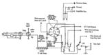
The schematic for these modifications is shown below. I can be contacted at w4bws at arrl dot net.
Related Comments
You must be logged in to leave comments.
Latest Links

|
HFU HF Underground“We seek to understand and document all radio transmissions, legal and otherwise, as part of the radio listening hobby. We do not encourage any radio operations contrary to regulations. Always consult with the appropriate authorities if you have questions concerning what is permissable in your locale.”HF Underground is the best online resource for what's happening on shortwave. &... READ MORE
- Robert Nickels (W9RAN), 03/67/2022
|

|
Every Saturday morning the Vintage Single Sideband net begins on or near 3842 kilo CYCLES. The Vintage Sideband Net welcomes your tube type or hybrid radio of ANY age to check-in. Newer radios sold in 1979 or before OR have a rotary bandswitch knob, will be granted Vintage Status by Net Control and are OK to check in. However, if you try to sneak in with a modern radio you WILL suffer the wrath of... READ MORE
- Robert Nickels (W9RAN), 03/64/2022
|

|
The members of the MCRN are dedicated to the preservation, restoration and operation of vintage ham transmitters, receivers, related equipment and ham radio history. The MCRN starts at 7:30 CDT every Saturday morning on 3.885MHz following the WA9ZTY Vintage AM Group session. All net traffic is conducted in the amplitude modulation mode only. Regular net control stations are N9CQX (Ne... READ MORE
- Robert Nickels (W9RAN), 03/61/2022
|
|
Your #1 source for new replacement can capacitors and complete re-cap kits for any vintage radio. If we don't have it listed, we can make it - just tell us what you need using the "Request for Quote" tab on our website. Thanks for your business!... READ MORE
- Robert Nickels (W9RAN), 02/34/2022
|
|
Old QSL Cards - W9GFQ, W0GFQ Leo Meyerson... READ MORE
- Bradley Stone (stonebs), 10/280/2020
|